Making Custom Brims for Difficult Parts
I decided to print out a couple of Stian Wahlvaag's Surprise Eggs to put in my kids' Easter baskets this year. I went with the excavator because A) it's got a lot of fun moving parts, and B) it's an excavator, and who doesn't love excavators?
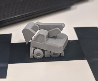
I got the eggs to print just fine on my first try, but the excavator itself gave me some troubles. All of the mechanical bits worked great, but one part of the bumper kept failing. That one spot had a very small footprint, so it kept getting knocked loose during the print. It took me several attempts to get things worked out for a successful print, but it also gave me a chance to work on designing a custom brim to help print small footprint objects! Here's a photo of the one that finally worked next to an older attempt (with a much smaller custom brim) that failed:

 So, here's how I made my custom brim. First, I opened up Blender and imported the model. Then, I pressed Numpad 5, Numpad 1 to get a look at it from the Front Orthographic view. I took a look at it from this perspective to make sure that the bottom of the object was actually at 0 on the Z axis, which will be important later. If I needed 100% precision, I could have gone into edit mode and selected the bottom faces, then looked at their position on the N data panel, but when you're zoomed in this far, we can eyeball it to a precision that's far greater than the printer can handle, so I figured that was good enough.
 My next step was to make an object for my brim. I hit Shift-A and selected Mesh -> Cube. At this point, I would usually move my cube around and get things in rough position, but in this case, I want the cube's origin to remain at 0, 0, 0, so I instead hit Tab to go into Edit Mode and moved it around in there. I positioned my cube so that it was overlapping with the front bumper (one of my problem spots). To make it easier to move around, I hit g (to grab it) and then his shift-z to move it not along the Z axis. That made it really easy to slide around on the XY plane and get it into position.
Next, it was time to mess around with the top and bottom faces of this shape. There are two things that I needed to do here: set the total height of my brim object to whatever my first layer height was going to be (or close enough that the slicer would both respect its existence and only make it 1 layer tall), and prepare to round off all of the corners. It's important to round off the corners to prevent curling, as sharp corners like to curl upwards when the object cools and can cause problems during the print.
 First, I adjusted the height. My first layer was going to be .15 mm tall (my .25 mm nozzle doesn't work super well with a .2 mm first layer), so I selected the top face of the cube and went to the N data panel, then entered .15 on the Z field of the Transform section. Since I had this face selected already, I went ahead and set its Mean Crease to 1.00 as well, to make my "rounding" step later work well. Now that my top face was in good shape, I basically did the same thing to the bottom of the cube, except that I set the Z position to 0 for that one (giving me my nice .15 mm tall brim).
So, why did I set that mean crease value? I did that to keep those faces flat after I added my Subdivision Surface modifier! I cranked the Subdivisions View setting up to 3 so that the corners of my cube would be smoothly rounded, but it probably didn't really need that level of fidelity.

 So, with the corners of my cube nicely rounded (to prevent curling, as mentioned earlier), it was time to move the corners around to get a shape that I liked. To do that, I pressed Ctrl-Tab and changed to Edge select mode, then selected each corner edge and moved them around to stretch out my not-circle. I wanted it to be long enough to touch the entire length of the bumper, but I also wanted to make sure that it wasn't going to wrap all the way around to the "inside" of it, where it would be difficult to remove later. To move these corners around easily, I just used that same g, shift-z trick from earlier, so that I wouldn't accidentally move the edges up or down on the Z axis.
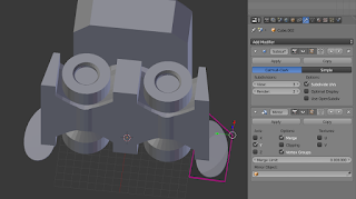 Now that I had the brim for one of the bumpers built, it was time to do the same on the other side. When I was looking at this model initially, I noticed that it was symmetrical along the Y axis. So, instead of making another brim for that second bumper, I figured that I could just let the Mirror modifier to do it for me! So, with the brim object selected, I added that modifier, changing the Axis from X (the default) to Y. Because I left the origin of my brim at the same spot as the excavator's origin (0, 0, 0 in this case), the mirror flipped it around to the exact right spot, with no extra effort required. I like no extra effort required!
 And that's all it took! With that brim object in place, I went back to Object mode and selected everything, then exported it as an STL. With my new STL built, I pulled that into Slic3r and sliced it (without enabled Slic3r's brim feature, since I had just built my own!), then fired off that gcode to get my first successful print of this model (although the cab's overhang was a little bit steep for me... I'm wondering if a .4 mm nozzle might not do better with that)!


Comments
Post a Comment