New Thing: Yet Another Mini Storage Solution
 After printing 50+ minis for Gloomhaven, I realized that I needed some way to store (and, more importantly, transport) all of these little guys! There are a ton of great mini storage solutions already on Thingiverse, but none of them were precisely what I wanted... so I decided to design my own. Also, after all of this work recently with complex organic shapes, I was looking forward to designing something that was purely mechanically functional in nature =)
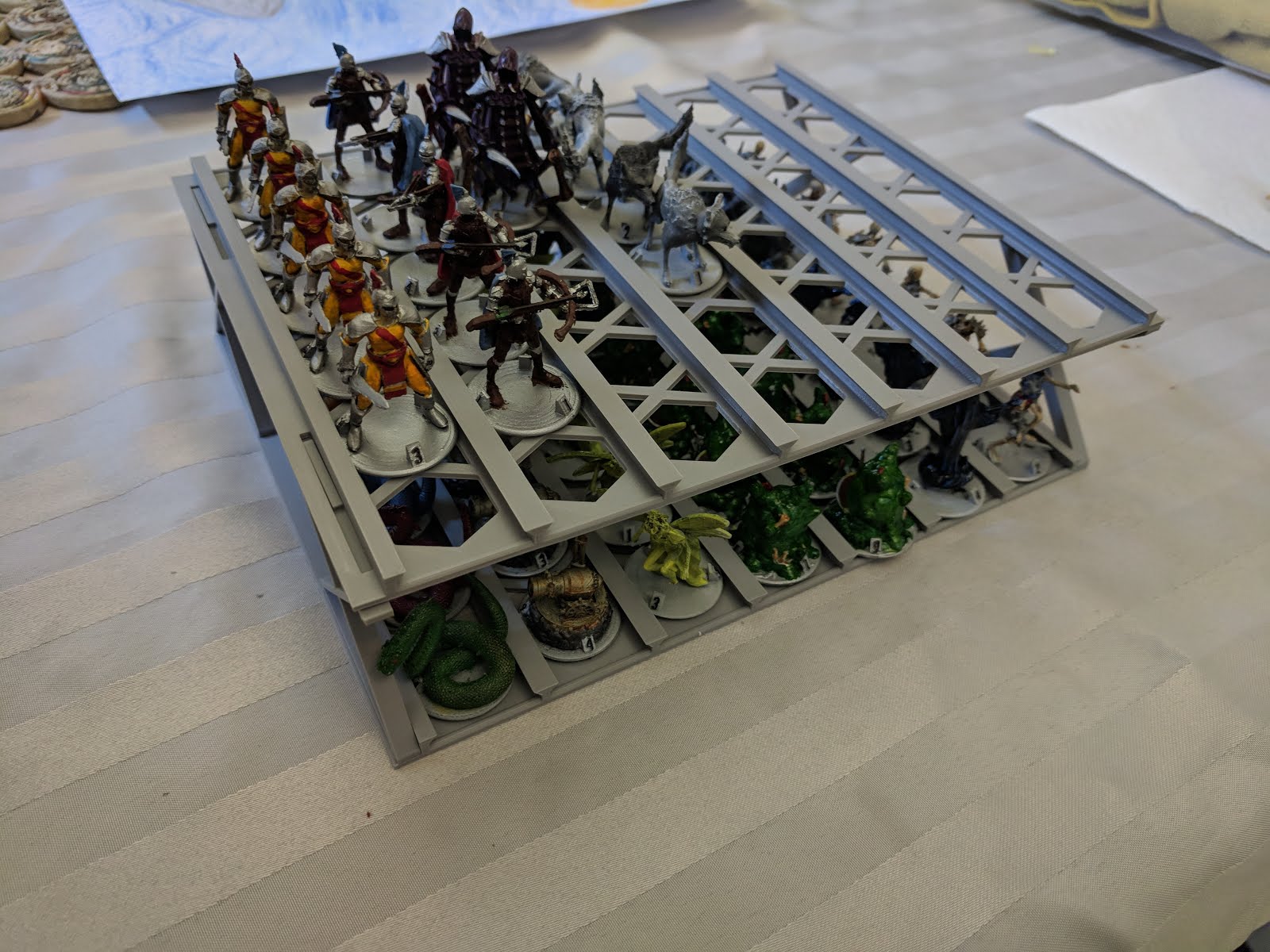
I had a tote box from Costco that I wanted to use for my minis, so I designed this to fit inside of it. I measured the inside dimensions (at the bottom, because I learned from last time) and decided that I should make it fit half of the tote, that way it would be printable in a single piece on my Prusa ;)
Those other options on Thingiverse were a great source for ideas. In the end, I decided that I really liked the "slide-in channel" design that Thetrebor used, but I wanted my sheets to be stack on top of each other inside of my tote box, rather than inside of a frame. Also, I wanted to make it printable without supports, so I tapered the "locks" at the tops of my channels so that they protruded at a 45 degree angle, instead of completely horizontally. I also designed my spacers so that the slot/key mechanism would work with a key to one far side of the spacer, so that it could be printed flat on the bed with that side down. To support stacking N layers high, the spacers take up one half of the slot when sticking up from the bottom and the other half when sticking down from the top.
When I decided to build this, I decided to do it with as many modifiers (and as little geometry) as possible. So, I started with a plane that was 210 x 165 (the measurements that I had determined would fit nicely within my box) and applied the Solidify modifier to it, making it 1.5 mm thick. I then decided that it was time to make the borders between each channel, with the aforementioned tapered tops. I knew that I was going to need 2 of them - one for the inside with locks on both sides, and one for the outside with a lock on only one side. So, I made some more planes and shaped them like this (these are two separate objects, which will be important soon!).


Next, I had 2 more objectives: make it require less plastic and make it stackable. To make it use less plastic, I made 2 cutouts and then repeated them in a pattern, a hexagon and a pair of triangles. I made the hexagon large enough to take up most of the channel, but small enough that a miniature's base couldn't slide through it on accident. I then arrayed those hexagons twice, first along the X axis and then again along the Y axis. This gave me 7 rows of hexagons that I could use to cut holes into the sheet.

Those hexagons left a lot of solid space in between them, so I decided to add the triangles. I made them by adding another plane (at the same spot as one of my hexagons), dissolving one of the vertices, then sliding the remaining one over to make an isosceles triangle (hint: select the isolated vertex and use the n data panel to move it to 0 on the X axis). Then, while still in Edit mode, I slid the whole thing up on the Y axis so that the edge of my triangle lined up with the top of the hexagon. I did that in Edit mode so that it the geometry would be moved relative to the origin of the object, so that I could apply the Mirror modifier along the Y axis to create the second triangle. I then moved to Object mode and slid my pair of triangles along the X axis until it looked like it was right in the middle of two of the hexagons (in hindsight, I should have just grabbed them and moved them 17 units over, which is 1/2 of the distance in my array along that axis), then I played around with the X axis scaling on my triangles until I liked the way they looked. Next, I added the two array modifiers like before, so that I'd have a whole bunch of them in the appropriate spaces.

That left me with the risers. I knew that I wanted a 5 cm gap between trays, so I made an initial version with round columns. That didn't work out so well, as they just weren't stable enough. So, version 2 had the construction-style trusses that I ended up running with, which worked much better. Now, I just had to work out their dimensions.
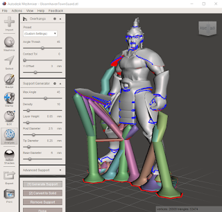
 I know that I could've used the Pythagorean theorem to figure out exactly how long my angled trusses needed to be to give me a 5 cm lift (and how aggressively to distort the ends of my support beams), but I also knew that I could do it with way less effort, so that's what I did. I drew the cross section for my beams, which was a basic L shape, then I used Solidify to make it really long. Next, I made a few large "cubes" and arranged them like this. You can't tell in the screenshot, but there's a 5 cm gap between the bottom cube and the top cube. With those cubes in place, I cloned and angled my support beams (and added top and bottom bars, just below the cubes), letting them stick way into the cubes. You can probably guess what I did now: Boolean Difference. I used those cubes to cut away all of the excess support beam, leaving me with perfectly fitting support beams. Adding on keys at the top and bottom gave me my final spacer shape.


This comment has been removed by a blog administrator.
ReplyDelete