New Thing: Numbered Bases for Gloomhaven, Part 2
As promised, here's the continuation of my post about how to make numbered 25 mm bases for tabletop RPGs! In the first post, I wrote about how to make the top half of the base; this post will focus on making the bottom half and on making the joint that allows them to easily snap together! As I begin this post and think about re-creating the original design, I've been struck with an idea: I bet I could improve it too, and that's exactly what I'll do.
 To begin this process, I decided that I want to duplicate the top half. While in Object mode, I selected it and pressed shift-d and then pressed esc to leave the duplicate exactly in place. Next, I pressed numpad-/ to focus on only my duplicate, which basically hid every other object from the view until I press it again.
 Next, my goal was to invert the shape while keeping the inner faces the same size (so that they'd look nice when the top and bottom halves are pressed together). To do that, I went into Edit mode, hit ctrl-tab and changed to edge select, then used alt-right-click to select the ring of edges immediately below the start of the taper. I then pressed g, z -2.8 to move it downwards 2.8 mm. Why 2.8? Well, I wanted this part of the base to be 1.5 mm tall. The smaller ring at the bottom (which will become the top) is at -1.5 on the z axis (you can find this out by selecting part of it and looking at the n data panel's local z axis value), so I want this ring to go down to -3. The ring is currently at -.2, so dropping it by 2.8 solves it!
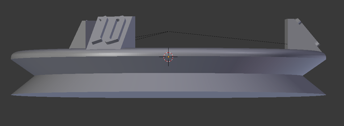
 That leaves me with an ugly shape though, as all the stuff at the top is still right where we left it. Well, we don't need it any more, so we can just get rid of it. To do this, I switched to vertex select mode through ctrl-tab, then pressed z to go into wireframe mode, pressed numpad-1 to get my view perfectly from the front, then pressed b to box select the top of the geometry. With the top stuff selected, I pressed x and and selected vertices to delete all of those vertices, then used z to change my view back to solid mode.
 It's looking better now, but it's still not right. If you look around, you'll quickly notice that the bottom is completely open. What you may have also noticed is that the color is off. That's because we've basically turned this shape inside out. Fortunately, they're both easy to resolve! While in edit mode, use alt-right-click to select the bottom ring and then press f to make a face. Next, press a to select all, then press ctrl-n to recalculate the object's normals. Normals are how Blender knows an object's inside from its outside. With those two quick steps done, we've got the easy part of the bottom completed.
 The next step is to make the mechanical interface that will allow the bottom of the base to connect to the top! If you press numpad-/, you'll be able to see everything again, and should find the bottom half of our base is perfectly aligned with the top half of it. Here's where I think that we can improve the original design a bit. We're going to have to create a cavity in the top half and some prongs on the bottom half to fill that cavity, but we can use better shapes than I did in the original version!
 First, we're going to need a block to cut out our cavity. Given that the top half of the base is 2 mm thick, I think that I'm going to make a 1.5 mm cavity. I also want my shape to get wider as it goes upwards, to help the prongs grip it better. I pressed shift-a and selected mesh -> cube to add a cube. Numpad-/ made it easy to focus on, so when I went to Edit mode I was able to easily move bits around. The default cube is 2 mm to a side, so I moved the top face downwards .5 mm by selecting it and pressing g z -.5. I wanted this to work with 2 long bars, so I selected it all and scaled it to 2.5 along the Y axis and 1.5 along the X axis. Finally, I know that the top surface of my bottom base is at -1.5 mm, so I selected the whole thing and moved it down .5 mm so that it would eventually line up.
 Next, to make the bulge, I pressed ctrl-r to add a ring-cut around the whole box (move the mouse to one of the side edges until the cut shows up, then click to put it there). I slid mine upwards a bit (-.3 seemed like a good height), then scaled that ring along the X-axis to 1.3. At this point, I unfocused and dropped back to Object mode, then I renamed my cube in the browser. I called it Cavity to make it easier to find later.

 With the cavity defined, I duplicated it and moved the duplicate off to the side by hitting shift-d, x -50. Then, I selected the top half of the base and added a Boolean modifier to it. I selected Difference and selected the Cavity object (not the duplicate with the number at the end). I changed over to the Carve solver, as it seems to handle coplanar faces better. After that, I selected the Cavity cube, then shift-right-clicked the base and hit ctrl-p to parent the cavity to the base. This made it so that whenever the base moved, the cavity would follow it. After that was done, I selected the cavity and pressed h to hide it. That left me with a good looking top! Next, it was time to make the prongs.
As a rule of thumb, you should leave about .2 mm of gap between two objects that you expect to interface after they're printed. So, that means that our prongs need to be .2 mm smaller than te cavity object. So, to that end, I went over to the Cavity copy that we made (which I've renamed as prongs), then in Edit mode I grabbed the top face and lowered it by .3 mm. Since ceilings can have some droop, it's good to give them a bit extra flex space. Next, I decided that it was too hard to move everything precisely .2 mm inwards given my current setup, so I made a quick change.
 I moved over to vertex select mode via ctrl-tab, turned on wireframe with z, then selected all of the right half of my model with a box select (press b), just like I did earlier. Then, I flattened them out by pressing s x 0 (scale these things to 0 on the x axis). Next came a bit of math.

I want my prongs to be 1 mm thick. The n data panel shows me that my now vertical column of points is at 1.65 mm. The point at the bottom left of the prongs is at -1.5 mm. So, to get my desired thickness, I had to move my points from 1.65 to -.5. I pressed g x -2.15 to move those points over the desired amount. Next, I pressed a to select everything, then slide it all over to the right by .2 mm. The Z and X axes were looking good, so now it was time to shrink along the Y axis.
 To do this, I pressed numpad-7 to look at it from the top down. Then, I used the same wireframe-box select trick to grab all of the vertices on the top and move them down .2, then grab all of the bottom vertices and move them up .2. When I was done, I had my new prong dimensions. The last step was to add the Mirror modifier on the X-Axis, to give me my second prong.
 At this point, it was time to put the prongs in place on the bottom half of the base. I first hid the top half of the base by clicking the little eye icon next to it in the navigator. I then selected the prongs, then used shift-right-click to select the bottom half of the base. Then, in the n data panel, I right-clicked on one of the axial location fields and selected copy all to selected. That should scoot the prongs right back into place over the bottom of the base.

At this point, we're pretty much done! You can go back into Wireframe mode (via z) and select various parts to ensure that they're going to fit together as intended. When you're happy with the fit, you can export the two halves separately. First, select the bottom and the prongs, then go to File -> Export -> STL. On the left, ensure that Selection Only is checked, then save the file. Next, hide those bottom parts by pressing h (or clicking the eye in the browser next to each one), select everything else (press a), and export that in the same way!
Edit: Well, writing this in real time means that I put the whole tutorial together without a test print! Just like in the first half, I've now discovered an issue and need to adjust things, and rather than go back and change the steps that I've already written, I'll show how I make the changes to the model!
After I printed it, I found that the elite base couldn't snap onto the top; the prongs just had too much resistance. So, I selected them and then went into Edit mode, then selected the left most edge and moved it .1 mm along the X Axis (so that it wouldn't need to bend as far when inserting it. For good measure, I grabbed the edge above that and scooted it over by .3 mm and up by .1 mm, so that there'd be more of a taper for insertion (since my cavity ceiling had .3 mm of clearance, I felt safe moving a single edge upwards a bit). Here's a screenshot comparing the old shape to the new one.
 This situation was a bit frustrating when it comes to blogging (although it was a good chance to show how easily things like this can be changed), but it's an example of why I love 3D printing! My design was flawed, and I was able to expose that flaw and remediate it in a single afternoon! The new version worked much better, requiring a bit of firm pressure to snap together (that'll relax after repeated use), but not snapping anything off! Once it's on there, the tapered cavity means that the prongs aren't under constant pressure, but it holds the elite base on just fine.
The .blend file for this project is available to my patrons, so please consider joining if you've got a few dollars to spare and appreciate my work!
 To begin this process, I decided that I want to duplicate the top half. While in Object mode, I selected it and pressed shift-d and then pressed esc to leave the duplicate exactly in place. Next, I pressed numpad-/ to focus on only my duplicate, which basically hid every other object from the view until I press it again.
 Next, my goal was to invert the shape while keeping the inner faces the same size (so that they'd look nice when the top and bottom halves are pressed together). To do that, I went into Edit mode, hit ctrl-tab and changed to edge select, then used alt-right-click to select the ring of edges immediately below the start of the taper. I then pressed g, z -2.8 to move it downwards 2.8 mm. Why 2.8? Well, I wanted this part of the base to be 1.5 mm tall. The smaller ring at the bottom (which will become the top) is at -1.5 on the z axis (you can find this out by selecting part of it and looking at the n data panel's local z axis value), so I want this ring to go down to -3. The ring is currently at -.2, so dropping it by 2.8 solves it!
 That leaves me with an ugly shape though, as all the stuff at the top is still right where we left it. Well, we don't need it any more, so we can just get rid of it. To do this, I switched to vertex select mode through ctrl-tab, then pressed z to go into wireframe mode, pressed numpad-1 to get my view perfectly from the front, then pressed b to box select the top of the geometry. With the top stuff selected, I pressed x and and selected vertices to delete all of those vertices, then used z to change my view back to solid mode.

 Next, to make the bulge, I pressed ctrl-r to add a ring-cut around the whole box (move the mouse to one of the side edges until the cut shows up, then click to put it there). I slid mine upwards a bit (-.3 seemed like a good height), then scaled that ring along the X-axis to 1.3. At this point, I unfocused and dropped back to Object mode, then I renamed my cube in the browser. I called it Cavity to make it easier to find later.
 With the cavity defined, I duplicated it and moved the duplicate off to the side by hitting shift-d, x -50. Then, I selected the top half of the base and added a Boolean modifier to it. I selected Difference and selected the Cavity object (not the duplicate with the number at the end). I changed over to the Carve solver, as it seems to handle coplanar faces better. After that, I selected the Cavity cube, then shift-right-clicked the base and hit ctrl-p to parent the cavity to the base. This made it so that whenever the base moved, the cavity would follow it. After that was done, I selected the cavity and pressed h to hide it. That left me with a good looking top! Next, it was time to make the prongs.
As a rule of thumb, you should leave about .2 mm of gap between two objects that you expect to interface after they're printed. So, that means that our prongs need to be .2 mm smaller than te cavity object. So, to that end, I went over to the Cavity copy that we made (which I've renamed as prongs), then in Edit mode I grabbed the top face and lowered it by .3 mm. Since ceilings can have some droop, it's good to give them a bit extra flex space. Next, I decided that it was too hard to move everything precisely .2 mm inwards given my current setup, so I made a quick change.
 I moved over to vertex select mode via ctrl-tab, turned on wireframe with z, then selected all of the right half of my model with a box select (press b), just like I did earlier. Then, I flattened them out by pressing s x 0 (scale these things to 0 on the x axis). Next came a bit of math.
I want my prongs to be 1 mm thick. The n data panel shows me that my now vertical column of points is at 1.65 mm. The point at the bottom left of the prongs is at -1.5 mm. So, to get my desired thickness, I had to move my points from 1.65 to -.5. I pressed g x -2.15 to move those points over the desired amount. Next, I pressed a to select everything, then slide it all over to the right by .2 mm. The Z and X axes were looking good, so now it was time to shrink along the Y axis.
 To do this, I pressed numpad-7 to look at it from the top down. Then, I used the same wireframe-box select trick to grab all of the vertices on the top and move them down .2, then grab all of the bottom vertices and move them up .2. When I was done, I had my new prong dimensions. The last step was to add the Mirror modifier on the X-Axis, to give me my second prong.
 At this point, it was time to put the prongs in place on the bottom half of the base. I first hid the top half of the base by clicking the little eye icon next to it in the navigator. I then selected the prongs, then used shift-right-click to select the bottom half of the base. Then, in the n data panel, I right-clicked on one of the axial location fields and selected copy all to selected. That should scoot the prongs right back into place over the bottom of the base.
At this point, we're pretty much done! You can go back into Wireframe mode (via z) and select various parts to ensure that they're going to fit together as intended. When you're happy with the fit, you can export the two halves separately. First, select the bottom and the prongs, then go to File -> Export -> STL. On the left, ensure that Selection Only is checked, then save the file. Next, hide those bottom parts by pressing h (or clicking the eye in the browser next to each one), select everything else (press a), and export that in the same way!
Edit: Well, writing this in real time means that I put the whole tutorial together without a test print! Just like in the first half, I've now discovered an issue and need to adjust things, and rather than go back and change the steps that I've already written, I'll show how I make the changes to the model!
After I printed it, I found that the elite base couldn't snap onto the top; the prongs just had too much resistance. So, I selected them and then went into Edit mode, then selected the left most edge and moved it .1 mm along the X Axis (so that it wouldn't need to bend as far when inserting it. For good measure, I grabbed the edge above that and scooted it over by .3 mm and up by .1 mm, so that there'd be more of a taper for insertion (since my cavity ceiling had .3 mm of clearance, I felt safe moving a single edge upwards a bit). Here's a screenshot comparing the old shape to the new one.

The .blend file for this project is available to my patrons, so please consider joining if you've got a few dollars to spare and appreciate my work!


Hmm.. wonder if you could fit status markers on those somehow...
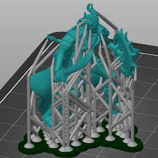
ReplyDeleteI use Gloomhaven Helper, so the idea never occurred to me! You could probably carve out little holder slots for the status markers, but that might make it difficult to fit some minis onto the bases. My Giant Viper model, for example, uses up the whole base. In fact, it obscures one of the numbered stands completely, but I decided that I liked it big so left it a little awkward to use (and I painted them all different colors to help differentiate them).
Delete