Tweaking Support Pads for FDM Printing
 When running an SLA print, the standard practice is to use a Pad, which is basically a few solid layers of very well cured resin, then have the model suspended above it on trees. This solid pad helps ensure bed adhesion, and probably does some other important functions that I haven't even considered... but we don't necessarily need it if we're doing an FDM print. In fact, if our model has a flat bottom, it can be really nice to have it directly on the print bed instead of floating above it!
 Fortunately, we can tweak the support pad in order to behave in exactly this way! The first thing that you'll want to do is open PrusaSlicer (with an SLA printer selected), then go to Print Settings tab and open the Pad section. Start out by enabling the Pad Around Object option.
 That will enable the basic "halo pad" but we're going to want to tweak a few of these other settings for our FDM printers. The first one is the Pad Wall Thickness. This setting is used to determine how tall to make the pad; I like to make it a bit shorter than my first layer is going to be, so .15 mm for my .2 mm first layer (tall enough that it will be respected by my FDM slicer, but short enough that it won't become 2 layers). This will give me a nice single layer connection for the bases of all of my support trees, which will really help them stay in place during the stresses of 3D printing. Older versions of PrusaSlicer seemed to also use this setting to specify the width of the pad, but that doesn't seem to be the case any more!
Next, you'll want to configure your Pad Connector Width. The support pad will have little tabs that connect it to your model; this setting determines how wide those tabs will be (the setting above it, Stride, controls the frequency of those tabs). For most models, you could probably get away without those tabs entirely, as the model probably has a decent footprint and the support pad will almost definitely have one... but they're really easy to remove and I like the security that they provide. After all, it seems like most FDM printing catastrophes begin with the model coming off the bed, and this is an easy way to help prevent that.
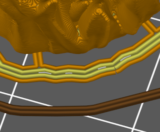
 I set mine to twice my nozzle width so that the printer will make two parallel lines for each connector tab. So, because I'm using a .4 mm nozzle, I set my Pad Connector Width to .8 mm, which sliced nicely into tabs that are two lines thick (as you can see). These connectors are super easy to trim with my Flush Cutters; I just stick the tips in between the pad and the model from the underside (flush side towards the model) and cut right through them.
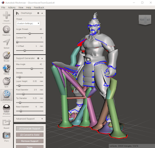
 Once your pad is set up, it's all about getting correct Supports settings for your printer (which is something that I'm still refining). If anyone's curious, here's a screenshot of the settings that I used for my most recent .4 mm nozzle print on my Prusa MK3. After I got support points in all of the critical spots, the print came together without any serious hitches!


Comments
Post a Comment